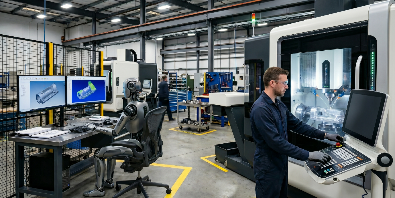
In Part 1, we explored how AI and manufacturing are converging, and how critical a solid software strategy is when you attempt to define Industry 4.0 for your shop floor. Integrating manufacturing industry 4.0 principles is not just about adopting new tools; it is about fundamentally rethinking your process.
In Part 1, I ended with a question.
Which of the five use cases describes your situation? Programming speed on prismatic work, real-time machine feedback, knowledge reuse, faster quoting, or a copilot for your team?
The answers that came back via DM’s and real conversations told me something important. Most people could name their problem clearly. Very few had asked the next question. Not what does this solve. But can my process actually support it?
That second question is what this the second part is about.
Where the Accountability Actually Sits
AI does not create a new category of manufacturing risk.
Scrap, rework, and non-conformance happen in every machining operation. They happened before AI existed. Robust **CNC simulation software** catches geometric and kinematic errors before the machine runs, and it does so effectively regardless of how the program was generated.
What AI-assisted programming changes is not the risk. It is where accountability sits when something goes wrong despite those safeguards.
When an experienced programmer makes a strategy decision, they can explain it. They chose this approach because of this material condition, this fixturing arrangement, this surface requirement. That reasoning is available. It is traceable. When something goes wrong, root cause analysis can reach it.
When an AI system proposes the same strategy, the reasoning behind that proposal may not be documented anywhere. The toolpath may be geometrically correct. The part may pass inspection. The process control record may still be incomplete.
In a regulated environment, an incomplete process control record is a compliance gap. Regardless of whether the part meets print.
The requirement is not that the AI explains its internal reasoning. The requirement is that your process remains controlled, validated, and traceable around whatever tool you use.
It is also worth being precise about what the AI actually decided versus what the CAM kernel computed. In most deployed programming acceleration systems, the AI proposed the strategy: operation sequence, tool selection, cutting parameters, approach to each feature. The CAM kernel computed the toolpath motion using deterministic algorithms. Simulation validated the motion. What simulation cannot reconstruct is the strategic reasoning behind the plan. That is exactly what a quality auditor requires when a non-conformance occurs.
"The AI recommended it and we ran it" is not a controlled process. The question is not whether AI was involved. The question is whether the process around it was defined, followed, and documented.
Why This Matters More Than the Part Cost
The cost of a process control gap in aerospace is not measured in individual components.
When a non-conformance cannot be traced to a documented, controlled decision, the investigation begins. Engineering review. Customer notification. In serious cases, fleet impact assessment. That process is expensive before a single rework hour is counted.
In a regulated aerospace manufacturing environment, an audit finding triggers corrective action requirements and surveillance audits under the quality management system. The downstream cost lands in contract risk, not just component cost.
In a job shop machining aluminium prismatic parts, an undocumented AI decision costs time and material. In a Tier 1 aerospace operation, the inability to explain and defend a strategy decision has a materially different profile. That asymmetry matters. It is why the rest of this article is written the way it is.
What the Standards Actually Require
Three standards govern this conversation. They are often cited and rarely read in detail.
AS9100 Rev D is the current quality management standard for Aviation, Space and Defence organisations, published by SAE International. It requires that production and service provision be carried out under controlled conditions. Those conditions must include documented information defining the results to be achieved, monitoring and measurement activities at appropriate stages, and actions to prevent human error. It requires identification and traceability of outputs throughout the manufacturing workflow. And it requires that any changes to controlled manufacturing processes be reviewed, approved by authorised persons, and documented.
None of those requirements prohibit AI. All of them apply to AI-assisted decisions with exactly the same force as to manually made ones.
AS9102B, the Aerospace First Article Inspection standard published by SAE International, requires that the first production article be inspected and documented against an approved manufacturing plan. That plan must include the processes, tools, and parameters used. Incorporating AI into a programming workflow is a process change. Whether it triggers a re-FAI requirement depends on how the change is characterised and agreed with the customer. That conversation needs to happen before the first AI-generated program reaches the machine, not after.
PPAP, the Production Part Approval Process developed in the automotive industry by the AIAG and formally adopted by many aerospace primes as a supply chain quality requirement, requires documented evidence that a manufacturing process can consistently produce a conforming part. For shops that supply primes requiring PPAP, AI-generated programs are subject to the same process capability documentation requirements as manually generated ones.
Flow-down makes all of this reach every tier of the supply chain. AS9100 Rev D requires organisations to communicate applicable requirements to their external providers. A subcontract shop that incorporates AI into its programming workflow without establishing documented control around those decisions is creating a gap that a prime contractor audit can surface.
If you cannot validate, control, and trace a machining decision within your process, you cannot certify it. That applies to AI-assisted decisions exactly as it applies to manually made ones.
A Note on the EU AI Act
The EU AI Act, Regulation (EU) 2024/1689, entered into force in August 2024 with staggered application running through 2027.
It establishes a risk-based framework for AI systems placed on the EU market, classifying them by the level of risk they carry. General manufacturing process planning software is not explicitly listed as a high-risk category.
The Act does apply high-risk status to AI systems that serve as safety components of products covered by EU machinery legislation. The key word is safety component. Systems that qualify under this pathway are those integrated into machine behaviour itself, such as autonomous CNC controllers that adjust motion in real time without human intervention, or AI-driven safety monitoring systems embedded in the machine tool.
AI-CAM process planning software, which proposes machining strategies for a programmer to review and approve before execution, is not typically integrated into the machine as a safety component. It operates upstream of machine control. The distinction matters. An AI system that modifies machine motion autonomously faces a different classification question than one that generates a strategy for human approval. Most current AI-CAM deployments sit in the second category.
That said, this interpretation is not settled. As AI-CAM systems move toward greater autonomy, with agentic systems beginning to attempt the full workflow without human review, the classification question becomes more complex. National competent authorities across EU member states are still developing guidance. Suppliers placing products on the EU market should seek their own legal assessment of their specific deployment before drawing conclusions.
The good news for suppliers already operating under a mature AS9100 quality management system is significant. The Act's documentation, transparency, and human oversight requirements align closely with what AS9100 already demands. The work you have already done is a strong foundation.
With that regulatory context in place, here are three practical tests for your next vendor evaluation.
The Three Tests
The three tests below are my own analytical framework, developed from user experience and the evidence reviewed for this series. They are not a published standard or a regulatory requirement. They are the questions I would ask in any vendor evaluation for a regulated manufacturing environment.
Do not ask whether a system can handle your work. Ask how it behaves when the physical reality of your shop floor contradicts what the model expects. Ask whether it can account for every decision in terms your quality team can document and defend.
Test 1: The Setup Awareness Test
For 3-axis and 3+2 work
Most AI-CAM systems analyse the CAD geometry to generate a machining plan. Geometry is what they know. What they do not have direct access to, unless it is explicitly modelled or measured, is the physical setup. The compliance of your specific fixture. The mass distribution of the workpiece in that orientation. The harmonic behaviour of a thin-walled section under cutting load.
If you read Part 1, you saw this illustrated with the thin-walled aluminium aerospace bracket. The toolpath was geometrically correct. Simulation passed. The part failed in production because the wall deflected under cutting load. Test 1 is the structured version of the question that example leaves open: when your system cannot see the setup physics, how does it tell you?
Published research consistently documents that workpiece deflection under cutting forces is a function of the specific setup, not just the material and the geometry. The same toolpath on two different fixtures, or two different clamping pressures, can produce different dimensional outcomes. A program that passes simulation on Monday can produce an out-of-tolerance part on Thursday when something changes in the setup.
Simulation validates geometry and kinematics. Advanced tools can model aspects of cutting physics, but full setup-level variability across real production conditions remains difficult to represent. A toolpath can pass every check and still fail in production because the physical conditions of the specific setup were not captured in the model.
The question to ask: How does your system account for non-modelled physical variables, clamping compliance, workpiece resonance, fixturing asymmetry, when generating a strategy? And when it cannot account for them, how does it communicate that uncertainty to the programmer?
A controlled answer looks like this. The system flags when setup conditions fall outside its demonstrated reliable operating range. It produces a record that says, in effect, geometric clearance is confirmed but setup rigidity for this wall section is unverified and manual validation is required before running. The programmer documents what was validated, what was found, and what was changed. That is a controlled process.
An uncontrolled answer looks like this. "The programmer reviews it." That is not a process. That is a gap. Unless that review is defined, documented, and assigned to a specific authority, it will not satisfy an AS9100 Rev D audit on controlled production conditions.
One embedded test worth running. Can the system show accumulated rest material across all setups before a single line of NC code is generated, and can that output be logged as part of your process record? A system that cannot track rest material globally is leaving decisions undocumented downstream & potential risk of tool breakage.
Test 2: The Kinematic Awareness Test
For any system claiming 5-axis capability
In simultaneous 5-axis machining, a singularity occurs when the tool axis vector aligns with the direction of one of the machine's rotary axes. At this configuration, the inverse kinematics calculation that converts tool position and orientation into machine axis coordinates breaks down. There are either infinite solutions or no smooth continuous solution for the rotary axis positions.
The machine controller resolves this by executing a large, rapid rotary axis move within a fraction of a second. In most cases, this move approaches or exceeds the axis velocity limit. The controller responds with a following-error alarm and a controlled stop. Where the move stays within velocity limits, it still produces a velocity discontinuity in the toolpath that degrades surface finish and subjects the tool to sudden changes in cutting engagement.
The kinematic behaviour at singularities is specific to the machine's axis configuration, whether AC, BC, or AB and cannot be resolved from the CAD model alone. This is one of the reasons that autonomous simultaneous 5-axis programming remains the hardest challenge in **5 axis machining software**. What current commercial systems offer in the 5-axis domain is optimisation assistance: helping select tool orientations, suggesting strategies, refining feed rates. That is genuine value for **manufacturing process optimization**. It is not autonomous 5-axis strategy generation with machine-specific kinematic awareness. The distinction matters for how decisions are documented and validated.
The question to ask: When your system generates or suggests a tool axis vector for a 5-axis operation, does it do so with knowledge of your specific machine's kinematic configuration, including singularity avoidance during path generation? Or does it generate tool axis vectors and rely on post-simulation to detect kinematic problems after the fact?
A controlled answer looks like this. The system generates tool axis vectors with machine-specific kinematic awareness. Singular zones are identified and avoided during generation, not discovered in simulation. The reasoning behind each tool axis vector choice is available for the process record.
An uncontrolled answer looks like this. The system generates paths and relies entirely on simulation for kinematic validation. The AI drafted a path. Simulation caught a problem. The programmer fixed it. This workflow shows why **post processor development** and **CNC simulation software** verification must remain controlled. The process is acceptable if it is defined and documented as the intended strategy. It is not acceptable if it is presented as autonomous kinematic intelligence, or if the review and correction steps are not recorded.
Test 3: The Process Control Test
For any AI-CAM system in a regulated manufacturing environment
AS9100 Rev D does not prohibit AI. It requires process control. Decisions must be reviewed. Changes must be authorised. Outcomes must be verifiable. Responsibility must be clearly assigned.
An AI system can exist inside a controlled process. It cannot replace one.
The question to ask: Can you show a documented process, for a real part, that records what the AI suggested, what the programmer reviewed, what was changed before approval, and who held the approval authority?
A controlled answer looks like this. There is a defined review step. The reviewer has documented authority under the organisation's quality management system. What was accepted, modified, or rejected from the AI output is recorded. The approval record is retrievable for audit. The AI is inside the process. It is not above it.
An uncontrolled answer looks like this. The AI generates the plan, the CAM kernel computes the motion, the programmer runs simulation, the part is produced. No defined review step. No documented approval. No traceable record of what the AI decided and what the human accepted. This is a process control gap under AS9100 Rev D, regardless of whether the part passes inspection.
Before committing any AI-CAM system to regulated work, request a walkthrough of the complete documentation trail for a real completed job. What was generated, what was reviewed, what was changed, what was recorded, and what an audit trail looks like. That walkthrough will tell you more than any marketing presentation.
Green, Amber, Red
The framework below is my own analytical tool, not a published industry classification. Use it as a starting point for your own process risk assessment, mapped to your specific parts and quality requirements.
For readers who named their use case in Part 1: programming speed on prismatic work and knowledge reuse map to Green and low-Amber. Real-time machine feedback is Amber to Red depending on sensor integration and validation evidence. Simultaneous 5-axis work is Red under this framework until a system passes the Kinematic Awareness Test. Quoting and copilot tools sit outside the machining-risk classification but require their own process governance review.
Not all AI-CAM work carries the same risk. The tool that saves four hours on an aluminium bracket can create a process control gap on a titanium structural component. The framework maps AI-CAM capability to work type and risk profile.
Green: AI assistance delivers documented value. 2.5D and prismatic 3-axis work on familiar materials with well-defined tool libraries. Even here, validate claimed savings against your own part mix and document the outcomes. The University of Maribor systematic review (Simonič, Palčič and Klančnik, 2025, Strojniški vestnik, Journal of Mechanical Engineering) found that only 3 out of 51 AI in CAD-CAM studies used real-machine experimental validation as their primary methodology. As of this writing, no updated systematic review has reported a materially different finding. The 5.9% figure remains the best available independent evidence of where AI-CAM experimental validation currently stands. Vendor benchmarks are not your benchmark. The AI proposes. The CAM kernel computes. The programmer verifies. That verification must be recorded and assigned to a defined authority within the quality management system.
Amber: AI assistance requires visible logic and active validation. 3+2 positional work, moderately complex geometry, tight tolerances. Strategy logic must be visible and modifiable. Rest material must be verified across all setups before the process moves forward. The programmer is not reviewing output informally. They are validating it with full technical understanding of what the system proposed and why. That validation must be documented as a defined process step with a named authority. If the system's reasoning is not visible at this level, treat it as Red.
Red: AI output is a starting draft, not a program. Simultaneous 5-axis machining. Complex sculptured freeform surfaces. Novel materials. Non-standard fixturing. Any situation where the system cannot demonstrate setup-aware kinematic intelligence and where the complete validation process is not fully defined and documented. For mission-critical work, the Red boundary must appear explicitly in your process controls. Any system whose simultaneous 5-axis capability cannot pass the Kinematic Awareness Test above should be treated as Red, regardless of vendor claims or simulation results.
A note on where aerospace manufacturing actually sits.
Frames, ribs, spars, bulkheads, engine casings. The majority of aerospace structural components are programmed by deriving 2D geometry analytically from 3D surface models. The CAD model does not present discrete 2D prismatic features that map cleanly to the feature-recognition approach that most AI-CAM systems depend on. For roughing and semi-finishing, programmers derive the machining geometry from their own reading of the 3D model. For finishing, only surface-based simultaneous machining strategies apply. A system searching for classic prismatic features in an aerospace structural component will find very little to anchor its recommendations.
Until AI-CAM systems can operate effectively on derived geometry and autonomous surface-based strategies, they address the periphery of aerospace programming workload, not its centre.
If a vendor cannot tell you which zone their system operates in for your specific parts and processes, that is your answer.
What Must Improve
These requirements reflect the same process discipline that mature manufacturing tools have already demonstrated. The gap exists not because AI is uniquely deficient, but because the validation methods for AI-assisted tools are still developing. Closing that gap is the condition for adoption, not a permanent barrier to it.
These are not conditions unique to AI. They are what any new tool must demonstrate to earn a place in a controlled, validated, traceable manufacturing process. AI is not exempt because it is new.
Process control records that integrate with your quality management system. A documented record of what the AI proposed, what the programmer reviewed, what was modified, and who held approval authority, in a format that supports non-conformance management and corrective action under AS9100 Rev D. This is not a demand for the AI to explain its internal reasoning. It is the same process discipline that applies to any controlled manufacturing tool.
Uncertainty signaling tied to defined thresholds. Systems must indicate when input geometry or setup conditions fall outside the range where the system has demonstrated reliable performance. Without this, there is no documented basis for deciding when to trust the output and when to escalate to full manual programming. That escalation decision must be part of the defined process, not left to individual judgment on the day.
Independent validation data for simultaneous 5-axis applications. Performance data validated by parties independent of the vendor, across different machines, geometries, and fixturing conditions, evaluated against defined acceptance criteria. The Maribor review found that only 5.9% of AI in CAD-CAM studies used real-machine experimental validation as their primary methodology. Until independent 5-axis validation data exists at production scale and complexity, the Red zone classification for autonomous AI in simultaneous 5-axis applications is the only defensible position in a regulated environment.
Setup-specific validation capability. The ability to validate AI-generated strategies against the physical conditions of the actual setup, not just the CAD model. General knowledge of machining physics is not a substitute for process-specific physical validation. This requires sensor integration and defined validation procedures that most current commercial deployments do not yet provide.
Surface-based machining capability at production scale. The dominant programming mode in aerospace structural manufacturing is not prismatic feature recognition. It is analytical geometry derivation followed by surface-based simultaneous machining. This reflects thirty years of direct observation across aerospace CAM programmes. Until AI-CAM systems address this domain at production complexity and volume, their application in aerospace remains peripheral. Any technology claiming serious aerospace credentials should be asked directly: can your system generate strategies for components where the machining geometry does not exist as a discrete feature in the CAD model?
Some emerging systems are beginning to build toward process-compatible architectures, with explicit confidence indicators, decision traceability, and human approval gates before output reaches the shop floor. That is the right direction. The test will be whether these approaches hold under production conditions and independent validation.
That is the same test every other system in this space must pass.
The Standard
The instinct machinists develop over years, to question, to verify, to assume nothing until proven on the machine, is the same instinct formalised in aerospace certification systems.
Do not incorporate a tool into a process it cannot support. That means defined review steps, traceable decisions, documented approval authority, and validation evidence that stands up to audit.
That is not a higher standard for AI than for any other tool. It is the same standard. AI is not exempt from it.
The machines will get smarter. The validation methods will develop. The systems that build visible decision records, signal uncertainty honestly, and validate against real setup conditions will earn a place in controlled aerospace manufacturing.
Vendors define capability. Aerospace defines what is certifiable. Those are not the same thing.
You define what your process can support.