Let me start with a simple analogy.
You write a letter in Microsoft Word. You want to print it. You connect the printer, but it needs a driver before it understands what to do. You install the driver. It works.
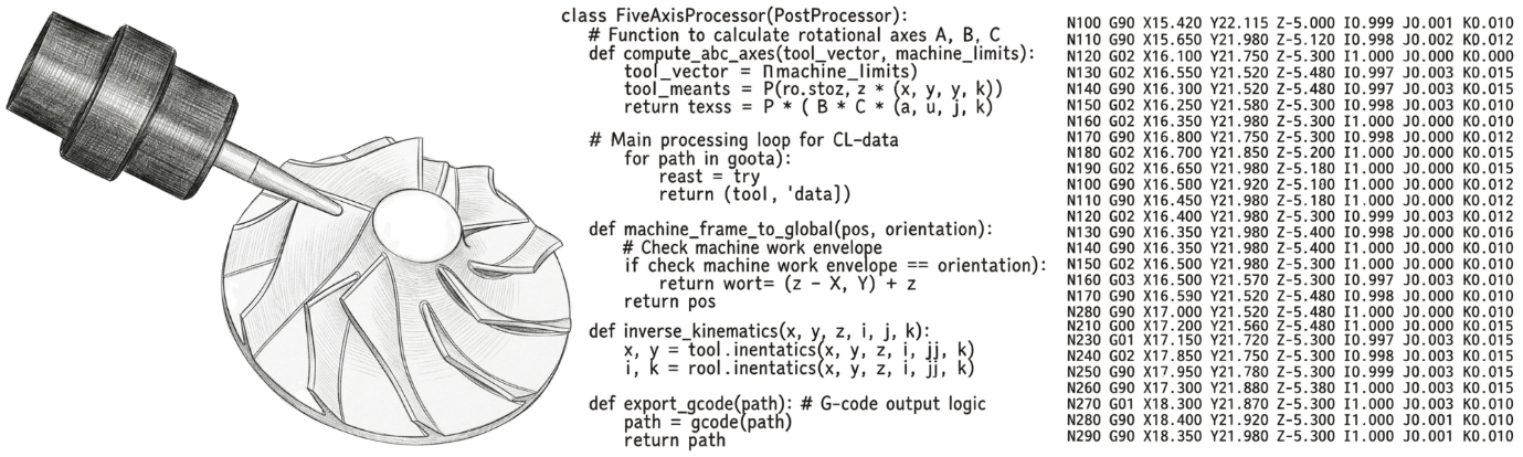
That driver is your post-processor. It converts your CAM toolpaths into G-code that your specific controller can read and execute.
Simple idea. Complicated reality. And the gap between those two things is costing Indian manufacturers more than anyone wants to admit.
A confession from 30 years of hiring
In my career so far, I have interviewed over a hundred people who listed "post-processor developer" as prominent skillsets in their resume.
The reality - fewer than 5% could build one from scratch.
The rest? They could open an ASCII file, change something in the header, adjust the footer. That was the extent of it.
This is not their fault. It is a structural problem. The industry has never been honest about what post-processor development actually requires.
After years of working alongside genuine experts, I arrived at three things you must have. All three. Not two.
- Deep CNC and machining knowledge. G-codes, M-codes, controller functions, the specific way Fanuc, Siemens, Heidenhain, and Mitsubishi each interpret the same command differently.
- Thorough knowledge of the CAM system. Not just how to operate it, but how its toolpaths behave internally and what the cutter location data actually contains at the output stage.
- A real programming language. C, C++, or Python. Post-processor languages are modest in structure, but they follow the same logic and syntax as mainstream languages. Without that foundation you are editing text and hoping.
In India, finding one person who genuinely has all three qualities is extremely rare.
Companies try to bridge the gap through training. Most, eventually hit a wall. It is why so many Indian CAM operations still route post-processor requests back to their global headquarters. The companies that can support customers end-to-end in India are those that have built this capability locally & these companies are the ones that are successful. They are only a few. I can count them on the first three fingers.  They stand out precisely because of it.
Why posts are encrypted, and why that is the right call
This comes up constantly in different forums. People are frustrated they cannot open and edit their 5-axis post-processor.
The encryption exists for a reason.
A wrong edit in a 3-axis post gives you a bad part or a broken tool. A wrong edit in a simultaneous 5-axis post can crash a spindle worth more than most people's homes, break a tool mid-cut in an aerospace component, or injure someone on the shop floor. In short if you do not know how to work with a post-processor and try to edit it, the results can be catastrophic.
CAM companies runs dedicated multi-day courses just to teach engineers how to configure and edit their generic 5-axis posts. The mathematics involved include vectors and matrices that most CNC programmers have never encountered. Most of these training are pretty basic and serve as a foundation to people with those 3 qualities I discussed earlier to become full fledged expert post processor developers.
Encryption is the post developer saying: this is not a place for improvisation. That is not arrogance. It is engineering responsibility.
3+2 and simultaneous 5-axis are not the same problem
This is the most important thing I want you to take from this article.
A post-processor that handles 3+2 work reliably is not a post-processor that works for simultaneous 5-axis. They are different documents solving different categories of problems. Treating them as the same is one of the most expensive assumptions in advanced manufacturing.
In 3+2 machining, the post works in discrete events. It positions the rotary axes to a fixed angle, outputs a CYCLE800 on a Siemens, a G68.2 on a Fanuc, or a PLANE SPATIAL on a Heidenhain, and then runs 3-axis code inside that tilted plane. The rotary axes lock. The kinematic problem is solved once per operation. Manageable work.
Simultaneous 5-axis is a different category entirely.
The post now delivers a continuous, uninterrupted stream of tool orientation data across thousands of blocks. Every block is a decision. Every decision interacts with the one before it and the one after it. The rotary axes are moving while the tool is cutting. The controller is doing its own real-time kinematic compensation on top of everything the post has already decided.
That layering is where problems become hard to diagnose and genuinely expensive to fix. For the shop owner, this is not an abstract engineering concern. It is the reason a machine that cost several crore rupees (For people who donÔÇÖt understand the Indian Rupee, 1 Crore equals 100-110 thousand US Dollars) produces parts that fail CMM inspection. It is the reason a programmer spends three days debugging a program that simulated perfectly. It is the reason an aerospace contract gets a quality rejection that nobody can explain.
Something most CAM users have never heard of
Here is something that three decades in CAM product development and implementation taught me, and that almost never gets discussed in public.
Most people think the post-processor is where kinematic transformation happens. It is not always the case.
In many modern CAM architectures, there is a layer that sits between the toolpath output and the NC code generation stage. Call it a kinematic solver. Its job is to take the cutter location data, the tool tip positions and orientation vectors that the CAM system generates and resolve them into actual machine axis values before the post-processor writes a single line of G-code.
This layer handles things the post-processor was never designed to manage cleanly on its own. Solution selection across thousands of consecutive blocks. Axis wind-up tracking. Limit-aware kinematic solution choices. Smooth reorientation when the machine approaches a physical constraint mid-cut.
When this layer exists and is properly configured for your specific machine geometry, simultaneous 5-axis output is significantly more reliable and more consistent. When it is absent, or when the CAM system leaves these decisions entirely to the post-processor, the burden on the developer multiplies considerably.
This is also why specialist firms like ICAM, Manus and IMSpost built entire standalone platforms around exactly these problems. Their Rotary Turn-Around logic, their automatic retract-and-reorient features, their limit-prediction capabilities, all of these exist because the gap between toolpath and reliable NC output is real, and it is larger than most users realise.
The question to ask your CAM vendor is direct. Where in your software stack does machine-specific kinematic transformation happen? How does your system handle solution selection and axis wind-up across a long simultaneous 5-axis program? And how has that been validated on my specific machine configuration?
If the answer is vague, that tells you something important. The post-processor cannot carry this load alone. And if nobody at your vendor can explain where it is being carried, there is a reasonable chance it is not being carried at all.
Modern controllers help. But they do not solve everything.
When Fanuc introduced G43.4, Siemens introduced TRAORI, and Heidenhain introduced M128, the heavy inverse kinematic mathematics that used to live entirely in the post-processing layer moved into the controller. The controller's RTCP function added real-time kinematic compensation on top of whatever the software had already resolved.
When both layers are working correctly, simultaneous 5-axis output becomes significantly more reliable.
When one is missing or misconfigured, the other cannot fully compensate.
Experienced developers on modern, well-integrated machines will tell you that RTCP genuinely narrowed the gap between 3+2 and simultaneous 5-axis post development. They are right. But moving the mathematics into the controller changes what the post and the kinematic solver have to get exactly right, not how much they have to do.
The post still has to manage mode choreography. It has to know when to activate TRAORI and when to cancel it. It has to know whether G43.4 and G68.2 can coexist in the same block sequence on a given Fanuc controller. It has to know that Fanuc expects IJK vectors for TCP while Siemens expects orientation vectors in a different format. A developer who treats them as equivalent makes a mistake they usually discover on the shop floor, not in simulation.
One machinist on a technical forum for post development described Fanuc's full requirement set as an "alphabet soup of G-codes," compared to Heidenhain where "you need two codes for five axes, done." That gap in controller philosophy is entirely the post developer's problem to bridge.
Beyond mode management, simultaneous 5-axis introduces solution selection. For any tool orientation, the mathematics give you more than one valid combination of rotary axis positions. The kinematic solver must choose the right solution. It makes that choice thousands of times across a complex program. A system without intelligent tracking does not know it has been winding the C-axis in one direction for hundreds of consecutive blocks. The accumulated travel brings the axis to its physical limit mid-cut. The machine faults. If that fault happens during a cutting pass rather than a rapid, the consequences range from a broken tool to a scrapped aerospace component that took hours to reach that point. That is not a technical inconvenience. It is a financial event.
Now add the Indian context. It gets harder.
A significant number of 5-axis machines sold in India are built in India. The mechanical engineering capability is real and growing. But the controller must be imported. And this is where a compliance reality enters the picture that almost nobody in the manufacturing conversation connects to post-processor complexity.
Controllers from European manufacturers, Siemens, Heidenhain, and Fidia, arrive as complete packages (Sometimes, if the function is not available, customers can just buy them without any complexity). The Indian machine tool builder gets full simultaneous 5-axis capability including RTCP. Challenging post development, but at least the controller is sharing the kinematic workload.
Controllers from Japanese manufacturers, such as Fanuc and Mitsubishi, operate under Japan's Foreign Exchange and Foreign Trade Act, which understandably classifies simultaneous 5-axis contouring capability as dual-use technology. Because these machines can produce highly complex components for aerospace and defence, obtaining full RTCP capability requires METI clearance, a structured licensing process involving detailed end-user declarations.
Many Indian machine tool builders and end-users successfully navigate this compliance process to unlock full controller kinematics. However, the administrative timeline introduces real friction. To get machines commissioned faster, or when end-user environments complicate the clearance process, machines are sometimes deployed with simultaneous 5-axis disabled in the firmware. They ship with 3+2 or positioning capability, while the full RTCP unlock waits on government review. Another situation would be a customer having an older generation machine and controller which is a 5 Axis Machine (Mostly attachments mounted on a 3 Axis Machine) which does not support RTCP.
The software kinematics trap
When RTCP is temporarily unavailable or administratively delayed or the controller just does not support, the controller cannot handle the real-time kinematic heavy lifting. That work falls entirely on the CAM software and its post-processor. The software must now compute, on every single block, the full inverse kinematic solution for the specific machine geometry, translating tool tip positions and orientation vectors into actual axis coordinates accounting for all pivot distances and offsets.
And this is where machine configuration becomes critical. For the shop owner, this is the moment where the choice of machine type directly determines the size of the software engineering problem you are signing up for.
A table-table machine, where both rotary axes are in the table and the spindle is fixed, is the most workable configuration for software-based kinematic compensation. The geometry is well-behaved. Demanding without RTCP, but solvable. Parts come out right. Contracts get delivered.
A head-table machine, where one rotary axis is in the table and one is in the spindle head, is significantly harder. The pivot geometry involves both the workpiece coordinate system and the tool axis orientation simultaneously, and they interact differently across the workspace. Errors at one tilt angle do not predict errors at another. Debugging is not linear.
A head-head machine, where both rotary axes are in the spindle head and the workpiece sits still, is the true test of an expert developer. The kinematic chain through two rotating head components is mathematically demanding. The compensation must be recalculated continuously as both angles change. Errors that are invisible at shallow tilt angles compound at aggressive ones. For a shop producing aerospace sculptured surfaces, those compounding errors show up in surface finish, in CMM reports, and eventually in customer rejections.
Now add a right-angle head to any of these configurations.
A right-angle head changes the effective pivot geometry of the entire system. The gauge length, the holder orientation, the relationship between the spindle axis and the actual cutting tool axis, all of these require a completely separate kinematic model for that specific tool configuration. The complexity does not grow incrementally. It multiplies. And so does the cost of getting it wrong.
This is exactly the challenge facing Indian machine tool builders who are producing highly capable hardware, but frequently need to deploy it in environments where full controller-side kinematics are pending compliance approval or just not available.
What this all means
India is building 5-axis machines. The ambition is real. The capital investment is real.
But a chain runs from that machine through the controller through the kinematic software layer to the part. Every link matters.
A weak kinematic foundation on a capable machine is like a powerful engine connected to a faulty gearbox. The power is there. It just does not reach the wheel.
The shops delivering genuine simultaneous 5-axis results in India today treated post-processor and kinematic solver development as a precision engineering exercise. The CAM Vendors they work with do have that rare developer with all three qualities. They understood their controller's RTCP status before commissioning. They asked the hard questions to their CAM vendor about how machine-specific kinematics are handled. They built a model specific to their actual machine geometry, not a generic approximation of it.
That work is not glamorous. It does not appear in a machine spec sheet or a CAM brochure. But it is the difference between a machine that delivers on its promise and one that quietly runs expensive 3-axis work on rotary axes that rarely move.
India has the capital and the ambition to dominate advanced manufacturing. But buying the hardware is only 50% of the equation. The other 50% is written in Python, C++, and kinematic mathematics. Until that half gets the same attention and investment as the iron it drives, the promise of Make in India in precision manufacturing will remain exactly that. A promise.